Metal on Ceramic Friction Surfacing Data for Printing Electronics

Contributors
Editors:
Hosting institution:
Other:
Project member:
- 1. University of Arkansas HiDEC
- 2. University of Arkansas
-
3.
 University of Arkansas at Fayetteville
Description
This repository is for data for an upcoming paper that presents work using micro friction surfacing for applying in-situ maskless metallizations and robust seed layers for electroless plating on demand to substrates like, aluminum oxide, aluminum nitride, and as fired LTCC, for fabrication of next generation power module and other high reliability electronic substrates. Macro photographs of the samples so fabricated can be found here;
https://zenodo.org/records/10308877
New generation power modules provide compact form factors while achieving multi kilovolt drive potentials at kiloamp currents.[1] However, their typical packaging and substrate metallization methods, such as thick film, direct bond copper, and active metal braze, limits attachment options and other manufacturing process requirements while incurring large processing costs and extended lead times for researchers and industry.[2]–[5] High speed micro friction surfacing allows for directly writing pure metal conductors and integrated passives, onto common insulating high reliability electronics substrates, supports additional layers of metallization and provides direct device interconnect before or after die fabrication and bonding, without bulk thermal annealing and without damaging the underlying substrate. Thus, making the next generation of power devices more tenable at the prototype level, and with further process refinements, at industrial scale.[6]–[13] This work highlights the importance of rapid and flexible prototyping for next generation power modules and high reliability electronics, and how finding new ways to use existing tooling can enhance fabrication options and potentially shore up semiconductor prototyping supply chain stability
1. Introduction
Current generation power modules and high-reliability electronics require rapid and flexible prototyping, but current fabrication methods using thin and thick film, ultrasonic soldering, direct oxide bonding and active metal brazing, have limitations due to exotic interface metallization, atmosphere control, and thermal cycling requirements during fabrication and deployment [2], [3], [5]. These limitations particularly apply to silicon carbide devices, where typical wire bondable aluminum, active metal brazed gold-titanium and direct bond copper substrate metallization schemes incur large fabrication costs and lead times while inhibiting rework of as fabricated substrates due to deep vacuum/ high temperature requirements and a substantial need for skilled manual labor [14], [15].
In this work, High Speed Micro-Friction Surfacing(HSMFS) is used to metallize substrates of aluminum oxide, aluminum nitride, and as fired LTCC, with millimetric to sub-millimeter, traces made of, copper, and gold. HSMFS enables relatively automated, single step fabrication of single layer electronic circuits with bond strengths that exceed thin and thick film methods and ultrasonic soldering, at a cost and lead time 20-50X less, without need for skilled labor. HSMFS is a downscaled extension of a broader class of methods known as "friction surfacing" wherein a rod or powder of a material to be coated onto a substrate, is stirred by rotating a tool, or "mechtrode" against the substrate, trapping the material to be deposited between the mechtrode and substrate surfaces.[1]–[3] The mechtrode can be either a wire of material that is consumed as deposition proceeds, or a non-consumable tool made of a hard material that resists wear during deposition. Heat is generated due to friction between mechtrode and substrate, and forging pressure is applied from a CNC motion platform. The combination of heat from friction, mechano-chemical activation, and forging pressure induced plastic deformation results in the shearing, viscoplastic flow and chemical and mechanical bonding of material from the mechtrode to the substrate being coated.
While there have been previous examples of friction surfacing metals onto ceramic substrates[4], [5], none have been used in electronics applications, and no characterization of relevant electro-thermal properties and endurance has been carried out. Additionally, the typically centimeter or larger deposit size scale of the mechtrode and consequently large supporting machinery in previous work has meant that the technique would be unsuitable for fabricating modern electronics. This large mechtrode scale results in excessive, evolved heat at the interface and thus high probability of heat shock damage to ceramic materials. Further, the relatively low mechtrode rotational speeds used in most prior works, results in very high forging pressures (hundreds of MPa), which typically far exceed the fracture toughness of common ceramic substrates. We have overcome these limitations and managed to obtain near bulk metallic electronic properties in as deposited track widths as small as 0.5mm, and metallization thicknesses from nanometers to 10's of microns on frangible substrates without damaging the substrate or compromising its electro-thermo-mechanical endurance.
2. Materials and Methods
2.1 Materials and tools
For this study the raw materials used to produce the printed prototype as fired circuits were provided by Tommy's Watch and Jewelry via Stuller Precious Metals, (1.6mm copper, #43-6421:100000:T and 0.6mm gold wire, #WIRE:9698:P) and The University of Arkansas High Density Electronics Center (HiDEC), (Dupont 1mm thick 951 LTCC, Stellar Industries 0.5mm thick 99% aluminum nitride, and 0.5mm thick 96% alumina ceramics).
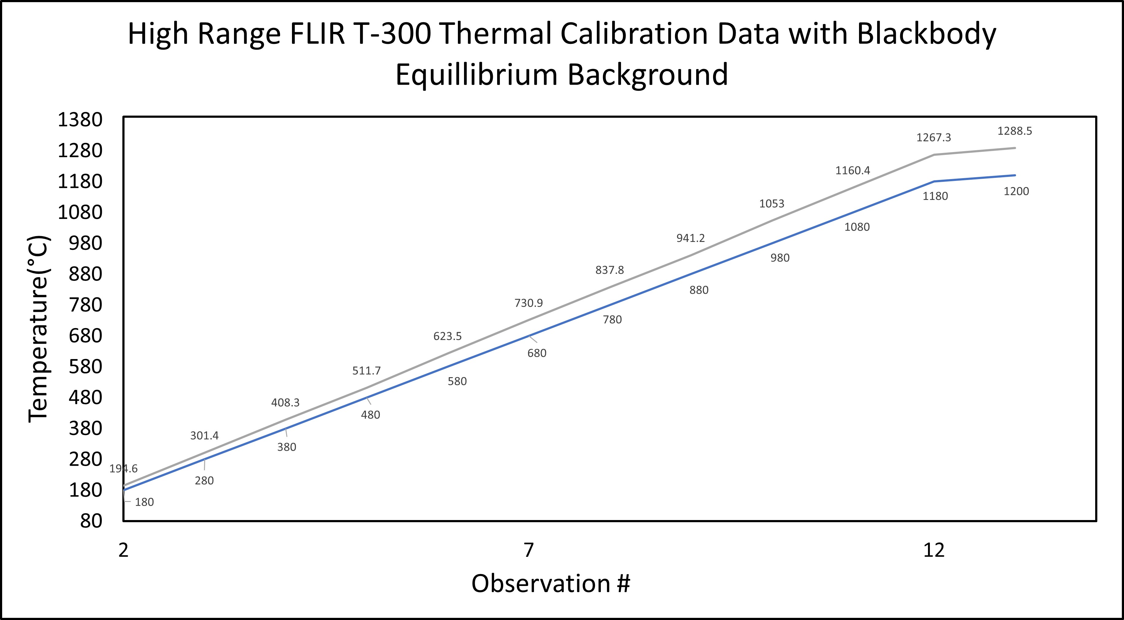
The process parameters for printing tracks of copper and gold on the three substrates of interest were explored using a genmitsu 1610 minimill with a Dremel "multipro" 30,000 RPM rotary tool as it's spindle, and a 26 gauge 1070 spring steel sheet covering the mill bed between the aluminum t-slotbed and the ceramic substrate being printed on, purchased on amazon. Each substrated was held in place with a set of binder clips to keep it firmly in position nad flat against the spring steel sheet during deposition. Each deposition process was recorded in thermal video(Flir-T300) (courtesy of Dr. Darin Nutter) with a microscope camera(Opti-Tekscope OT-HD) and in real time macro video (Nikon D750). Subsequent profilometry (Dektak3030) electrical resistance (Fluke 77), current handling testing, taklife and ACS723 current sensor, and Flir-T300 camera (courtesy of Dr. Darin Nutter), and film strength (Kapton pull tests) measurements were performed with tooling available at HiDEC.
Temperature data were extraced via optical character recognition using the script here:
https://github.com/mahydraal/OCRDataExtractor
it deploys tesseract OCR and relatively simple python script with tkinter to provide a graphical user interface to select a region of a video, scrub it for noise, convert it to black and white, and then read character data from the user selected region.
2.2 Determination of printing parameters
Metals, copper and gold, were deposited on substrates of 96% alumina, 99% aluminum nitride(Al-N) and fired 951 LTCC, from wires of 1.6mm and 0.6mm OD respectively, via high speed micro friction surfacing (HSMFS). Spindle RPM was set open-loop constant to 30K RPM, and surface feed velocity was varied between 15, 45 and 75 mm/minute at a constant ratio of X-Z feed distance of 80 to approximate a constant normal force at the stall torque of the Z axis motor of the motion frame in open loop mode. Each surface feed velocity set point was tested 3 times for each metal substrate combination. Each metal and substrate combination were cleaned with 90% IPA and 90% Acetone and Di rinsed then blown dry with nitrogen before deposition.
Friction surfacing is a solid-state joining process that involves rubbing two surfaces together at high speeds under pressure, creating a bond between the two surfaces without melting them, stereotypically shown in figure. The process can be used to join similar or dissimilar metals and alloys, metals and ceramics, and organics, and is particularly useful for joining materials with high melting points, such as titanium and nickel-based alloys without obtaining fusion and melting temperatures and without protective atmosphere. This process generates significant waste heat from friction and plastic deformation, which is useful for monitoring and controlling deposition consistency, thus real time thermographic videos during each test were collected using a FLIR T-300 thermal camera, and optical character recognition on it's display to obtain insight into the deposition temperature trends at the substrate-feedstock interface and better tune the surface feed-velocity at constant RPM to obtain electronic continuity in the as deposited metallic tracks on each ceramic substrate type. Real time macro videography was performed on each test to provide post-facto analysis and record any anomalies that would not be representative of typical performance.
An appropriate spindle speed for deposition must be selected as well as appropriate vertical and linear feeds and speeds for the mini mill in micro friction surfacing. This is generally due to the need for a specific surface energy threshold associated with frictional heating and mechanical surface activation to be obtained between the feedstock and the substrate. This surface energy must exceed the free energy of reaction for diffusion and bonding to occur between the atoms of the substrate and those of the feedstock. A list of energies of formation for various transition metal carbides and oxides, necessary for bonding of metals to carbide and nitride sub-states by friction surfacing is shown.
In short, by controlling spindle speed surface feed rate, and providing a constant down force by constant Z-X feed rate ratio on the minimill, it is possible to set a constant rate of heat evolved at the friction interface between the feedstock and substrate. If this heat evolved exceeds the heat of formation of a bonding compound of interest for long enough, the reaction of interest can proceed and a tenacious bond between metal and substrate can form. The details of accurately modeling heat evolved in friction surfacing, given the details of a specific deposition system and feed stock geometry are elucidated well elsewhere, [29], [30] so we will not go into them here. The primary point being that one can approximate appropriate deposition parameters for almost any material combination, knowing the free energy of formation of an appropriate bonding phase, and or the pressure-temperature phase diagram for the material pair of interest.
2.3 Characterization and measurement of test films
Bond strength of the HSMFS deposited films of copper and gold were tested initially by simple kapton tape pull testing, thereby assigning a minimum failure stress on film bond strengths. Temperature trends recorded during the deposition via thermography were correlated with resultant film resistivities and average height profiles and cycling performance for each set of parameters, each metal and each substrate; the most consistent and robust parametrization results were used in subsequent experiments to fabricate basic current carrying tracks with a mix of soldered and wire bonded terminals to demonstrate feasibility of HSMFS for rapid prototyping of electronics.
2.3.1 Electrical resistivity extraction and profilometry
Each material deposition was followed by profilometry (Dektak3030) at 3 points along each track, averaging the resultant maximum heights to determine film thickness and calculate sheet resistivity from resistance measurements on the multimeter(Fluke 77).
2.3.2 Maximum ampacity testing
Each printed specimen was terminated with copper tape, and soldered/wire bonded respectively. A taklife DC benchtop power supply was used to supply DC 31 volt power at up to 11 amps of current. An Arduino and high current shunt resistor current sensor measured the current flowing through the printed track, and acted to provide automatic control of current ramp up time. The current through the printed track was stepped up by the Arduino in steps of 25 milliamps every 60 seconds to provide time for thermal equilibration and avoid substrate fracture. This process continued until the track failed due to shorting, thermal breakdown, or electromigration failure.
Files
HR_BBEFlirT300.jpg
Files
(3.5 MB)
| Name | Size | Download all |
|---|---|---|
|
md5:ccc51e7a2c367c591bb8f849d1185178
|
32.2 kB | Download |
|
md5:aab86e8f82dd2dfaf404950a6b3e2e9f
|
22.6 kB | Download |
|
md5:0e6606a84c7dea393d42593f248ce7e7
|
20.3 kB | Download |
|
md5:35315bfa14cac572ca682c0316074223
|
20.7 kB | Download |
|
md5:236260e17c5620b7e6247063b332251d
|
18.8 kB | Download |
|
md5:4987231c59f26c98f7b8b4116bdb28bc
|
18.4 kB | Download |
|
md5:db3eb6a06ed0e8505237b536b1d03316
|
20.3 kB | Download |
|
md5:6ad01efd8154d65a72518c06f839de3c
|
17.9 kB | Download |
|
md5:7f4e21e8198a19b628e36c3aafec3424
|
18.2 kB | Download |
|
md5:61da94f56173b8d3bef64762e70b7796
|
18.4 kB | Download |
|
md5:95d3ce8038e1ac866126ce11ba797cd9
|
19.0 kB | Download |
|
md5:e1a6aa592d10301393fa394e05178a4e
|
19.1 kB | Download |
|
md5:ff95f4ec6f4d0fd933c5c5b822c32949
|
19.7 kB | Download |
|
md5:d8a7bafa9a9fa43b7262523c116c4c5b
|
19.1 kB | Download |
|
md5:f23b8830201e015af8fbcfef762c6e17
|
18.5 kB | Download |
|
md5:a485c4b14f2c67c38f6f13e935e71b27
|
18.6 kB | Download |
|
md5:54acb9e63bad294b49f87d5252e70802
|
18.4 kB | Download |
|
md5:70b1ded03aef779351f549a5534da970
|
18.8 kB | Download |
|
md5:5f9e9b258145e3eccfb529b163254a60
|
18.5 kB | Download |
|
md5:2e7a327d9c769864607f0221a0bf8a86
|
17.8 kB | Download |
|
md5:6af1068ec15b8aa0102b8aa52f3c8b52
|
17.7 kB | Download |
|
md5:8b89ca871d80ff061f6a537e08a01fdb
|
17.6 kB | Download |
|
md5:b03d3db6a0436c9701400bccd8a66f63
|
20.5 kB | Download |
|
md5:441da1c259711ffef3a8a1dfcae47e44
|
22.1 kB | Download |
|
md5:d462ee6b03fa910fc9ad252200dc33f5
|
21.9 kB | Download |
|
md5:8262907443ddef511701c8cb14c07c69
|
19.9 kB | Download |
|
md5:6bba5cb34a632ee8ef400592e037510a
|
12.4 kB | Download |
|
md5:3211b334b2582889bb264f6a8dfb21af
|
21.7 kB | Download |
|
md5:83ec348a111910eedd322a316e6edd67
|
19.0 kB | Download |
|
md5:979aae8cff8e7aab664392bd895f17d6
|
19.2 kB | Download |
|
md5:4968cba9dfa334c95d47d52cf8930a41
|
19.0 kB | Download |
|
md5:e0abd079de5b23c9d84485c7b84a9ab7
|
18.8 kB | Download |
|
md5:34ad67b16408fe1d4885525e958708a5
|
18.4 kB | Download |
|
md5:843eb9546b3c9694fbcc51b478521c53
|
75.0 kB | Download |
|
md5:f7586f1f917caa5f2ff6a5bec4a1c249
|
18.8 kB | Download |
|
md5:40e0a99bc832a38afad0f1bffc8b1c78
|
19.6 kB | Download |
|
md5:865ce85398071904cffeab8eecf0fa29
|
18.6 kB | Download |
|
md5:57c6ec78ff17513af3060642cf272e6c
|
18.2 kB | Download |
|
md5:366134212fdfd7a628957f65c20a9e95
|
19.1 kB | Download |
|
md5:4219ef492e8497b009dd28ea6ad694b0
|
25.2 kB | Download |
|
md5:fd7b0e40ecbe989ef99662bbf8ea636d
|
18.1 kB | Download |
|
md5:5ed7bb487e629abe08d3545e3c9894fd
|
18.3 kB | Download |
|
md5:47756dbd165972c5327b5c31c34f65b1
|
17.9 kB | Download |
|
md5:8ed298154ac8c4191990dc242de4b0b8
|
18.6 kB | Download |
|
md5:0ed79ad2787d721f826f7e8330f7ad97
|
18.5 kB | Download |
|
md5:cc4ff6dde997278b0e9522bc549cfc5d
|
18.7 kB | Download |
|
md5:de55599926db6f3bb0092f622af3a29a
|
18.0 kB | Download |
|
md5:c2e2f20fbabfae12db40e6b0e1783743
|
18.1 kB | Download |
|
md5:8cec4061b6fa0fa2ed999cc870cdbe1c
|
18.0 kB | Download |
|
md5:f47b163dba898565cd5497796999d483
|
17.9 kB | Download |
|
md5:8cf0a12f15ec24b6a9ca3f3a200329ae
|
18.1 kB | Download |
|
md5:1754237240890d4f467c742fcd937948
|
18.0 kB | Download |
|
md5:ce52721503d2e0fc30a247acab6e30c9
|
36.9 kB | Download |
|
md5:3b41023639fd973ed7f04e9a7f93bc78
|
19.5 kB | Download |
|
md5:94483105f540ad7395d96bb5aa254410
|
19.9 kB | Download |
|
md5:e9130f2f679fd056d2b6c809191e4fb1
|
19.9 kB | Download |
|
md5:0fffa180c28947d910a8440db6793c8e
|
26.1 kB | Download |
|
md5:433fc03cb118cb46e8a0352c9aa268b8
|
21.1 kB | Download |
|
md5:43c2b9750d8ef4c6dc5c697055d18001
|
18.5 kB | Download |
|
md5:6578175981c93ecd4c764fa995af2879
|
18.6 kB | Download |
|
md5:31e4cdd7865a10a4b41904893eae3e0a
|
22.0 kB | Download |
|
md5:581f06b69617f6956616c047fc12a0ba
|
18.6 kB | Download |
|
md5:584ac25d0b448dbcf703ab7a42c26b0f
|
18.6 kB | Download |
|
md5:f76bec848339a1ca708edd14fb68fb30
|
18.5 kB | Download |
|
md5:e3adf9ac66e26a9b16b1c2bb8eee131b
|
28.4 kB | Download |
|
md5:26f71c0564caaf8dc0c10a92ef8a25c1
|
18.7 kB | Download |
|
md5:f3cec1bcdc4106561c091098871d3440
|
19.0 kB | Download |
|
md5:7f90a62eb06e3fb3be6d9a4bb9d03647
|
18.9 kB | Download |
|
md5:42ccfd70d4fee8a2179ec10def1c5fa6
|
18.4 kB | Download |
|
md5:4049b297185bc9b2227473cc5370ee0d
|
18.3 kB | Download |
|
md5:38715679e65e1eabac91ab89a0a09596
|
18.2 kB | Download |
|
md5:5f297c392cb7a55e500b3cb6b7ed18a0
|
18.3 kB | Download |
|
md5:62f382fd640aa2b7c093da7f73a3103c
|
18.0 kB | Download |
|
md5:4d06539a48a5f76a6cbea2778c5c9243
|
18.0 kB | Download |
|
md5:628b2a3eabaebc3947ea7354ab3b457c
|
44.1 kB | Download |
|
md5:83eb77d60a063e81c784342daecacd77
|
84.5 kB | Download |
|
md5:23a033df7de426578150b9102611f429
|
411.3 kB | Preview Download |
|
md5:c26af6c8e21125932080dcaaada94496
|
428.2 kB | Preview Download |
|
md5:239fa16a02fd05fc8b6293bc3e1c2415
|
460.7 kB | Preview Download |
|
md5:9e2732995abce6747e7317bd774f7e5b
|
440.8 kB | Preview Download |
|
md5:022beeb873906c6be73f9a79f1625c6e
|
25.1 kB | Download |
|
md5:78d7f3b972541bdb568495779fcb21ba
|
24.9 kB | Download |
|
md5:82ac95b998d01c56556ca0370af5fcd9
|
26.3 kB | Download |
|
md5:33ab7a02daa28c57d5d395f2f2d8fc75
|
24.7 kB | Download |
|
md5:72e73b3af6bcace977e50fb3191b4f89
|
24.0 kB | Download |
Additional details
Related works
- Is referenced by
- Other: https://www.rotoforge.com/introduction/ (Other)
- Other: https://discord.gg/dN7EugaZ7U (Other)
- Is source of
- Video/Audio: https://www.youtube.com/playlist?list=PLxlbqMdRe6OVbtT3ehHzCJgsyfsY8-2mJ (Other)
Dates
- Created
-
2022-08